Tag Archives: Cisco Nexus Switches

CCIE DC Written – 1.1.a Link Aggregation – vPC Components

virtual port channels

Virtual Port Channel master really does begin with a knowledge of the components that make them up. This post assumes you are familiar with the very basics of virtual port channels – knowledge you have gained through CCNA/CCNP Data Center.

Here are the components of the vPC:

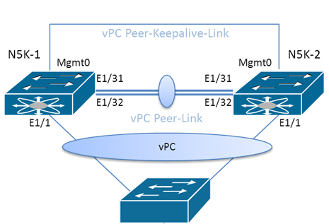
  • vPC peers – two switches that act as a single logical switch to the downstream device.
  • vPC peer link – a link between the vPC peers that is used to synchronize state. Consider two physical links in a port channel. MAC address table synchronization, as well as other control plane, functions synchronize over this link.
  • Cisco Fabric Services – this protocol is responsible for synchronization between the peers. CFSoE is run. STP is modified to keep the peer link ports forwarding.
  • vPC peer keepalive link – Layer 3 communication link between the vPC peers to act as a secondary test of connectivity.
  • vPC – the virtual port channel depicts itself to the downstream device as a single logical switch. The downstream device does not need virtual port channel support. It forms its standard port channel configuration.
  • vPC member ports – a member of the vPC on the vPC peer switch.
  • vPC domain – a numeric identifier for the vPC domain.
  • Orphan device – a device that is connected to only one peer in the vPC.
  • Orphan port – the switchport that connects to an orphan device.
  • vPC VLANs – the VLANs permitted to use the vPC. They must be permitted on the peer link.
  • Non vPC VLANs – the VLANs not permitted on the vPC.

Cisco Nexus Functional Planes – 5000 Series

Cisco Nexus

This post provides some detailed examples architecturally of the Cisco Nexus Functional Planes we initially discussed in the post – Cisco Nexus Functional Planes.

The control plane of the Nexus 5000 series contains many components you are already familiar with as a CCNA R&S:

  • The CPU
  • DRAM
  • Boot memory
  • BIOS Flash memory
  • Internal Gigabit Ethernet ports for connectivity to the data plane components

The data plane consists of:

  • Unified Ports Controllers (UPCs) – manages all packet-processing operations within the switch; these components are Layer 2 Multipath capable and support classic Ethernet, Fibre Channel, and Fibre Channel over Ethernet (FCoE)
  • UPC ASIC – handles the forwarding decisions and buffering for multiple 10-Gigabit Ethernet ports
  • Unified Crossbar Fabric (UCF) – responsible for coupling ingress UPCs to available egress UPCs; the UCF internally connects each 10-Gigabit Ethernet, FCoE-capable interface through fabric interfaces running at 12 Gbps

Remember, the control plane is responsible for managing all control traffic. Data frames bypass the control plane and are managed by the UCF and the UPC. Layer 2 control packets (BPDUs, CDP, UDLD, etc), Layer 3 control packets (OSPF, BGP, PIM, FHRP, etc), and storage control packets (FLOGI frames) are managed by the control plane supervisor.

For management access, Cisco Nexus Series switches can be managed in-band, via a single serial console port, or through a single out-of-band 10/100/1000-Mbps Ethernet management port.

Keep in mind that architectures will differ for different Nexus devices. For example, the Cisco Nexus 7000 devices use a distributed control plane approach. It has a multicore CPU on each I/O module, as well as a multicore CPU for the switch control plane on the (dual) supervisor module. The 7000 Series Switch offloads intensive tasks to the I/O module CPU for ACL and FIB programming. It scales the control plane capacity with the number of line cards. This avoids supervisor CPU bottleneck which could occur in a centralized control plane architecture.