Category Archives: CCNA Data Center

CCNA Data Center – Overlay Transport Virtualization (OTV) Terms

Overlay Transport Virtualization

Remember, we love OTV because it has the ability to connect Data Centers and make it appear as if they are connected Layer 2 domains. While there are other technologies that can do this, OTV is appealing for many reasons including its flexibility and simplicity of configuration and operation.

In order to understand the further study of OTV, you really need to be able to speak its language, and that means learning some terms that are commonly used to describe it. Here they are:

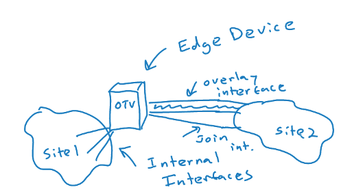
  • OTV Edge Device – this device takes the Layer 2 frames and encapsulates them in Layer 3 packets; in a “classic” implementation, the OTV device is a VDC of a Nexus 7K
  • OTV Internal Interface – a layer 2 interface on an edge device that connects to the VLANs that are to be encapsulated
  • OTV Join Interface – a Layer 3 interface that is used to join the two domains and discover the remote OTV device
  • Transport Network – the network connecting the OTV sites
  • Overlay Network – the logical network that connects the two OTV devices
  • Site VLAN – a VLAN that carries hellos between edge devices that might exist at the same site; it is best to use a dedicated VLAN for this role; this VLAN is not extended across the overlay
  • AED – the Authoritative Edge Device is elected for a site and is the designated forwarding edge device; devices maintain adjacency with each edge device in a site (site adjacency); they use the Site VLAN for this purpose; they also maintain the overlay adjacency using the join interface to a remote site

CCNA Data Center – Introducing Overlay Transport Virtualization (OTV)

Overlay Transport Virtualization

OTV is one of the many exciting new protocols we get to study in the CCNA Data Center. However, what the heck is it? What problems does it address? Let’s tackle that in this post.

Today, we often locate data centers a far distance from each other, and we might often need to make them look like they are the same structure from a Layer 2 perspective. For example, two virtualized services might expect to be able to find each other at Layer 2. In the past, solutions like EoMPLS (Ethernet over MPLS) and dark fiber were attempted. Unfortunately, these solutions present many issues of their own.

Enter the OTV solution. This technology does what we like to call MAC address routing. A control plane protocol exchanges MAC address reachability information between the data centers.

OTV does not require additional configuration to support multihoming and spanning tree protocol domain independence. OTV ensures that if there is an STP failure in one data center, it does not affect the other data center.

One of my favorite facets of OTV is the fact that the routing protocol in use in the control plane to make OTV function is IS-IS! This standards-based, OSPF competitor is making a real comeback. It was selected because it is a standard-based protocol, originally designed with the capability of carrying MAC address information in the TLV. Sadly, OTV does not get the credit in naming it deserves as most call the control plane protocol of OTV simply the OTV Protocol.

Interestingly, most deployments require no specific knowledge of IS-IS configuration (or even theory) since the routing protocol works its magic automatically as OTV is configured on your devices.

I will be back with other follow up posts on this technology including a look at terminology and configuration.

If you want to peek ahead and have some fun – check out the CBT Nugget below from yours truly!

Check out my very latest CCNA Data Center training (Late 2018) at CBT Nuggets:

https://www.cbtnuggets.com/it-training/cisco-ccna-data-center-200-155