Tag Archives: virtual port channels

CCIE DC – 1.1.a Link Aggregation – Configure Virtual Port Channels

This post examines the limitations you should be aware of when configuring virtual port channels. It also examines the configuration steps. This is part of the link aggregation section of the exam requirements in CCIE Data Center.
Aggregation

Our previous post on this subject focused on the control plane. You can find it here: https://www.ajsnetworking.com/ccie-dc-written-1-1/

Limitations

Before you dive right into the configuration steps, you should be aware of the limitations when it comes to your virtual port channels. These include:

  • In the “standard” virtual port channel – you use exactly two vPC peer switches – no more than that are supported. A later post here will cover the extended vPC technology, but this post does not consider that.
  • It is not possible for one of your peer vPC devices to participate in more than one vPC.
  • All ports for a given vPC must exist in the same VDC (Virtual Device Context). You cannot span a vPC across multiple VDCs.
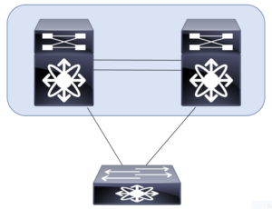
  • A 10 Gbps link is required for the vPC peer link. Typically, you should use at least two links in a port channel for this component.
  • A vPC is a Layer 2 construct. There is no support for the creation of Layer 3 vPCs.

The Configuration Steps

As you might guess, you should double-check all of your physical connections before launching into the vPC configuration. Ensure that your physical link(s) for the peer link are in place and healthy. Also, keep in mind that you make these configurations on each of the vPC peer devices.

Step 1. First, you must enable the vPC feature – you do this with the command: feature vpc

Step 2. Create the vPC using the vpc domain <domain_id> command

Step 3. Next, specify your peer keepalive link – this link can be in any VRF (including Management); use the command – peer-keepalive destination <remote_peer_ip> source <local_peer_ip> vrf <vrf_name>

Step 4. Configure your peer link. This is typically done with a port channel (as described above) as follows:

interface port-channel <port_channel_id>
switchport mode trunk
vpc peer-link

Step 5. Configure a port channel that leads to the downstream device; use the command vpc <domain_id> under the port channel

In the next post, I will walk you through a configuration on live equipment. We will also walk through the important vPC verifications you would want to perform at that time. As always, thanks for reading.

For even more information – check out this Cisco documentation at https://www.cisco.com/c/en/us/products/collateral/switches/nexus-5000-series-switches/design_guide_c07-625857.html
Pearson Education (InformIT)

CCIE DC Written – 1.1.a Link Aggregation – vPC Data Plane

vPC

Here is an important question about the data plane with your vPC. Is the vPC peer link (typically an EtherChannel) between your vPC peer switches used for forwarding data traffic? In a “normal” network condition, the answer is no. The vPC peer link is not used for the data traffic of the vPC and is considered to be an extension of the control plane between the vPC peer switches. The vPC peer link carries the following type of traffic:

  • vPC control traffic, such as Cisco FSoE, BPDUs, and LACP messages
  • Flooding traffic, such as broadcast, multicast, and unknown unicast traffic
  • Traffic from orphan ports

So we note that the peer link is used specifically for switch management traffic and occasionally for the data packets from failed network ports. This behavior of our vPCs enables the solution to scale because the bandwidth requirement for the vPC peer link is not directly related to the total bandwidth of all vPC ports.

What about loop prevention? One of the most important forwarding rules for a vPC is exactly about that as I have shown in the illustration above. Note this sample traffic flow:

  1. A packet enters the vPC peer switch via a vPC member port.
  2. The packet then goes to the other peer switch via the peer link
  3. The packet is then not allowed to exit the switch on the vPC member port.
  4. This packet can exit on any other type of port, such as an L3 port or an orphan port.

This rule prevents the packets that are received on a vPC from being flooded back onto the same vPC by the other peer switch.

What about this traffic from orphan ports? Understand there are two types of orphan ports for this discussion:

  • The first type of orphan port is the one that is connected to an orphan device and is not part of any vPC configuration. For this type of orphan port, normal switch forwarding rules are applied. The traffic for this type of orphan port can use a vPC peer link as a transit link to reach the devices on the other vPC peer switch.
  • The second type of orphan port is the one that is a member of a vPC configuration, but the other peer switch has lost all the associated vPC member ports. For this type of orphan port, the vPC loop avoidance rule is disabled. In this special case, the vPC peer switch will be allowed to forward the traffic that is received on the peer link to one of the remaining active vPC member ports.

CFSoE is used to synchronize the Layer 2 forwarding tables between the vPC peer switches. Therefore, there is no dependency on the regular MAC address learning between the vPC peer switches. CFSoE-based MAC address learning is applicable only to the vPC ports. This method of learning is not used for the ports that are not part of the vPC configuration.