Here is an important question about the data plane with your vPC. Is the vPC peer link (typically an EtherChannel) between your vPC peer switches used for forwarding data traffic? In a “normal” network condition, the answer is no. The vPC peer link is not used for the data traffic of the vPC and is considered to be an extension of the control plane between the vPC peer switches. The vPC peer link carries the following type of traffic:
- vPC control traffic, such as Cisco FSoE, BPDUs, and LACP messages
- Flooding traffic, such as broadcast, multicast, and unknown unicast traffic
- Traffic from orphan ports
So we note that the peer link is used specifically for switch management traffic and occasionally for the data packets from failed network ports. This behavior of our vPCs enables the solution to scale because the bandwidth requirement for the vPC peer link is not directly related to the total bandwidth of all vPC ports.
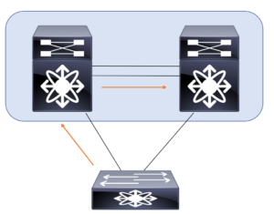
What about loop prevention? One of the most important forwarding rules for a vPC is exactly about that as I have shown in the illustration above. Note this sample traffic flow:
- A packet enters the vPC peer switch via a vPC member port.
- The packet then goes to the other peer switch via the peer link
- The packet is then not allowed to exit the switch on the vPC member port.
- This packet can exit on any other type of port, such as an L3 port or an orphan port.
This rule prevents the packets that are received on a vPC from being flooded back onto the same vPC by the other peer switch.
What about this traffic from orphan ports? Understand there are two types of orphan ports for this discussion:
- The first type of orphan port is the one that is connected to an orphan device and is not part of any vPC configuration. For this type of orphan port, normal switch forwarding rules are applied. The traffic for this type of orphan port can use a vPC peer link as a transit link to reach the devices on the other vPC peer switch.
- The second type of orphan port is the one that is a member of a vPC configuration, but the other peer switch has lost all the associated vPC member ports. For this type of orphan port, the vPC loop avoidance rule is disabled. In this special case, the vPC peer switch will be allowed to forward the traffic that is received on the peer link to one of the remaining active vPC member ports.
CFSoE is used to synchronize the Layer 2 forwarding tables between the vPC peer switches. Therefore, there is no dependency on the regular MAC address learning between the vPC peer switches. CFSoE-based MAC address learning is applicable only to the vPC ports. This method of learning is not used for the ports that are not part of the vPC configuration.