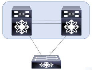
This post examines the limitations you should be aware of when configuring virtual port channels. It also examines the configuration steps. This is part of the link aggregation section of the exam requirements in CCIE Data Center.

Our previous post on this subject focused on the control plane. You can find it here: https://www.ajsnetworking.com/ccie-dc-written-1-1/
Limitations
Before you dive right into the configuration steps, you should be aware of the limitations when it comes to your virtual port channels. These include:
- In the “standard” virtual port channel – you use exactly two vPC peer switches – no more than that are supported. A later post here will cover the extended vPC technology, but this post does not consider that.
- It is not possible for one of your peer vPC devices to participate in more than one vPC.
- All ports for a given vPC must exist in the same VDC (Virtual Device Context). You cannot span a vPC across multiple VDCs.
- A 10 Gbps link is required for the vPC peer link. Typically, you should use at least two links in a port channel for this component.
- A vPC is a Layer 2 construct. There is no support for the creation of Layer 3 vPCs.
The Configuration Steps
As you might guess, you should double-check all of your physical connections before launching into the vPC configuration. Ensure that your physical link(s) for the peer link are in place and healthy. Also, keep in mind that you make these configurations on each of the vPC peer devices.
Step 1. First, you must enable the vPC feature – you do this with the command: feature vpc
Step 2. Create the vPC using the vpc domain <domain_id> command
Step 3. Next, specify your peer keepalive link – this link can be in any VRF (including Management); use the command – peer-keepalive destination <remote_peer_ip> source <local_peer_ip> vrf <vrf_name>
Step 4. Configure your peer link. This is typically done with a port channel (as described above) as follows:
interface port-channel <port_channel_id>
switchport mode trunk
vpc peer-link
Step 5. Configure a port channel that leads to the downstream device; use the command vpc <domain_id> under the port channel
In the next post, I will walk you through a configuration on live equipment. We will also walk through the important vPC verifications you would want to perform at that time. As always, thanks for reading.
For even more information – check out this Cisco documentation at https://www.cisco.com/c/en/us/products/collateral/switches/nexus-5000-series-switches/design_guide_c07-625857.html
One thought on “CCIE DC – 1.1.a Link Aggregation – Configure Virtual Port Channels”