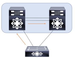
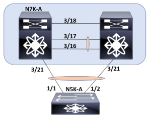
This post examines a sample configuration of a virtual port channel. This port channel is created between two Nexus 7K systems and downstream Nexus 5K systems. This is part of the link aggregation section of the exam requirements in CCIE Data Center. Below is the diagram you can use for reference in this example. We will only demonstrate the config of a single VPC peer since the other peer is simply a mirror of this configuration.
Our previous post on this subject focused on the configuration steps. You can find it here: https://www.ajsnetworking.com/ccie-dc-1-1-a-link-aggregation-configure-virtual-port-channels/
The Configuration
First, we will prepare the vPC keepalive link for this scenario. Do not be thrown off by the name of our VRF. This configuration does not technically fall under the vPC config (yet!).
N7K-A# configure terminal
N7K-A(config)#  vrf context VPC-KEEPALIVE
N7K-A(config-vrf)# interface ethernet 3/18
N7K-A(config-if)# no switchport
N7K-A(config-if)# vrf member VPC-KEEPALIVE
Warning: Deleted all L3 config on interface Ethernet3/18
N7K-A(config-if)# ip addr 209.165.200.225/24
Next, we will configure the vPC domain (after enabling the feature of course) and configure the peer-keepalive link we prepped.
N7K-A(config)# feature vpc
N7K-A(config)# vpc domain 10
N7K-A(config-vpc-domain)# peer-keepalive destination 209.165.200.226 source 209.165.200.225 vrf VPC-KEEPALIVE
Now, we configure a port channel between our vPC peers and configure it as the vPC peer link.
N7K-A(config-vpc-domain)# interface ethernet 3/16-17
N7K-A(config-if)# channel-group 10
N7K-A(config-if)# interface port-channel 10
N7K-A(config-if)# vpc peer-link
Next, we will head down to the N5K and configure a “plain ole” LACP port channel.
N5K-A# config t
N5K-A(config)# feature lacp
N5K-A(config)# int e 1/1-2
N5K-A(config-if-range)# channel-group 201 mode active
Now, it is time to configure the vPC on the N7K.
N7K-A(config-if)# feature lacp
N7K-A(config)# interface e 3/21
N7K-A(config-if)# channel-group 201 mode active
N7K-A(config-if)# int port-channel 201
N7K-A(config-if)# vpc 201
The Verification
You should note that you can and should perform verifications as you go along here. For example, you can verify reachability, check the port channels that are configured, and watch the progress of the vPC as you configure it. For brevity here, we will just end this post and this example with our critical show vpc command.
N7K-A(config-if)# show vpc brief
Legend:
     (*) - local vPC is down, forwarding via vPC peer-link

vPC domain id                          : 10
Peer status                            : peer adjacency formed ok
vPC keep-alive status                  : peer is alive
Configuration consistency status       : success
Per-vlan consistency status            : success
Type-2 consistency status              : success
vPC role                               : secondary
Number of vPCs configured              : 1
Peer Gateway                           : Disabled
Dual-active excluded VLANs and BDs     : -
Graceful Consistency Check             : Enabled
Auto-recovery status                   : Enabled (timeout = 240 seconds)
Operational Layer3 Peer-router         : Disabled
Self-isolation                         : Disabled

vPC Peer-link status
--------------------------------------------------------------------------------
id Port Status  Active vlans Active BDs
-- ---- ------ -------------------------------------------------------------
1  Po10 up      1,12 -

vPC status
------------------------------------------------------
id     Port        Status Consistency  Active VLANs
----- ------------ ------ ----------- ----------------
201    Po201       up      success     1,12
For even more information – check out this Cisco documentation at https://www.cisco.com/c/en/us/products/collateral/switches/nexus-5000-series-switches/design_guide_c07-625857.html